mirror of
https://github.com/UberGuidoZ/Flipper.git
synced 2024-12-22 22:40:14 +00:00
76 lines
3.8 KiB
Markdown
76 lines
3.8 KiB
Markdown
# Documenting adventures with the GPIO...
|
|
|
|
Official [GPIO layout](https://miro.com/app/board/uXjVO_LaYYI=/) created by [Aleksandr Kutuzov](https://discord.com/channels/740930220399525928/765282833744265246/993107060172542012).
|
|
|
|
# Sentry Safe plugin pinout<br>
|
|
(Flipper) 8/GND -> Black wire (Safe)<br>
|
|
(Flipper) 15/C1 -> Green wire (Safe)
|
|
|
|
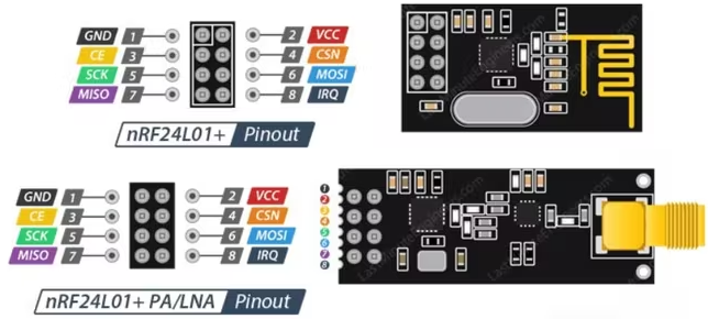
# Mousejack / NRF24 pinout
|
|
|
|
[More info on RogueMaster's repo](https://github.com/RogueMaster/flipperzero-firmware-wPlugins/tree/unleashed/applications/mousejacker). (Currently the only pre-compiled DFU with this included!)
|
|
|
|
2/A7 on FZ goes to MOSI/6 on nrf24l01<br>
|
|
3/A6 on FZ goes to MISO/7 on nrf24l01<br>
|
|
4/A4 on FZ goes to CSN/4 on nrf24l01<br>
|
|
5/B3 on FZ goes to SCK/5 on nrf24l01<br>
|
|
6/B2 on FZ goes to CE/3 on nrf24l01<br>
|
|
8/GND on FZ goes to GND/1 on nrf24l01<br>
|
|
9/3V3 on FZ goes to VCC/2 on nrf24l01<br>
|
|
IRQ/8 is left disconnected on nrf24l01
|
|
|
|
|
|
|
|
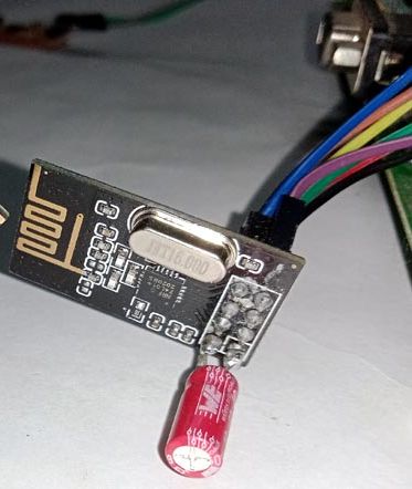
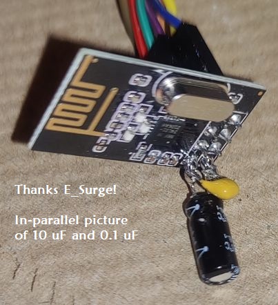
If the nRF model is acting a bit flakey, try adding a capacitor to the vcc/gnd lines! I've not tried the Plus model so it may have a bigger need for a cap. Otherwise, I haven't had any major issues. Anything from a 3.3 uF to 10 uF should do. (Watch your positive/negative placement! Negative to ground.) I learned if you wanna get fancy, include a 0.1 uF cap in parallel. The 3.3 uF to 10 uF will respond to slow freq changes while the 0.1 uF will respond to the high freq switching spikes that the larger one cannot. That said, a single 10 uF will likely suffice for the Mousejack attack. ¯\\\_(ツ)_/¯
|
|
|
|
|
|
|
|
|
|
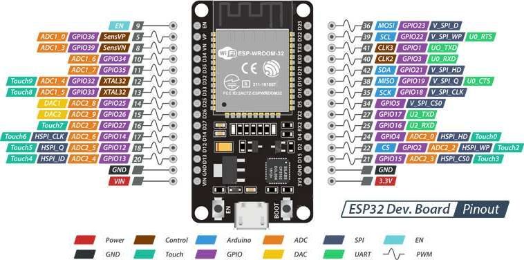
# ESP32-WROOM
|
|
|
|
|
|
|
|
NOTE: Use `old_hardware.bin` if flashing Marauder onto the ESP32-WROOM (thanks wyldgoat!)
|
|
|
|
<br>
|
|

|
|
|
|
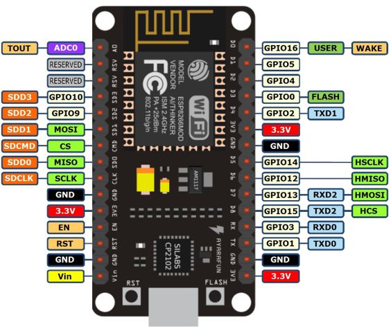
# ESP8266
|
|
|
|
|
|
|
|
## ESP32 / ESP32-WROOM / ESP8266 Pinout to Flipper Zero
|
|
(Thanks [E_Surge](https://github.com/ESurge) and wyldgoat for guidance!)
|
|
|
|
ESP32: 3 (RX0) -> FZ: 13 or 15 (these are TX pins)<br>
|
|
ESP32: 1 (TX0) -> FZ: 14 or 16 (these are RX pins)<br>
|
|
ESP32: GND -> FZ: 8 or 11 or 18 (GND)<br>
|
|
ESP32: 3.3V -> FZ: 9 (3.3V) ***OR*** ESP32: 5V -> FZ: 1 (5V)
|
|
|
|
Switch between UART Pins 13/14 and 15/16 setting in FlipperZero<br>
|
|
`(GPIO -> USB-UART Bridge -> LEFT -> UART Pins)`
|
|
|
|
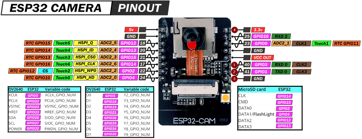
# ESP32-CAM (Camera)
|
|
|
|
|
|
|
|
## ESP32-CAM Pinout to Flipper Zero
|
|
|
|
CAM32: 1 (RX0) -> FZ: 13 or 15 (these are TX pins)<br>
|
|
CAM32: 2 (TX0) -> FZ: 14 or 16 (these are RX pins)<br>
|
|
CAM32: 3 (GND) -> FZ: 8 or 11 or 18 (GND)<br>
|
|
CAM32: 4 (3.3V) -> FZ: 9 (3.3V) ***OR*** ESP32: 5V -> FZ: 1 (5V)
|
|
|
|
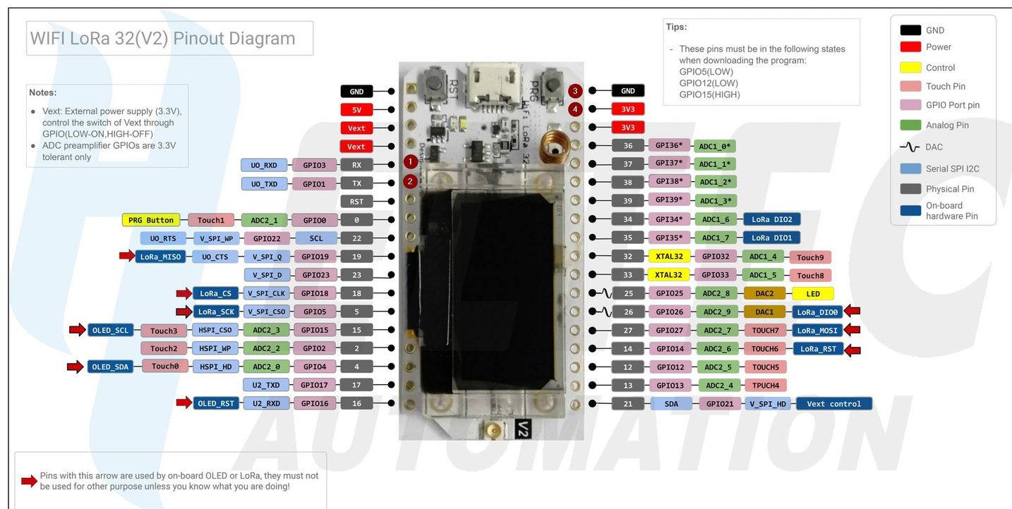
# LoRa ESP32 Wifi (Wifi + Bluetooth + LoRa 433 MHz)
|
|
|
|
|
|
|
|
## LoRa ESP32 Wifi Pinout to Flipper Zero (PENDING VERIFICATION)
|
|
LoRa32: 1 (RX0) -> FZ: 13 or 15 (these are TX pins)<br>
|
|
LoRa32: 2 (TX0) -> FZ: 14 or 16 (these are RX pins)<br>
|
|
LoRa32: 3 (GND) -> FZ: 8 or 11 or 18 (GND)<br>
|
|
LoRa32: 4 (3.3V) -> FZ: 9 (3.3V)
|
|
|
|
Switch between UART Pins 13/14 and 15/16 setting in FlipperZero<br>
|
|
`GPIO -> USB-UART Bridge -> LEFT -> UART Pins`
|