# Documenting adventures with the GPIO...
Official [GPIO layout](https://miro.com/app/board/uXjVO_LaYYI=/) created by [Aleksandr Kutuzov](https://discord.com/channels/740930220399525928/765282833744265246/993107060172542012). Official documentation [is here](https://docs.flipperzero.one/gpio-and-modules)!
Check out some unofficial boards by [DrB0rk](https://github.com/DrB0rk/Flipper-Zero-Boards) and an extender by [Speexvocon](https://github.com/Speexvocon/FlipperZeroHeaderExtender)!
# Sentry Safe plugin pinout
Plugin by [H4ckd4ddy](https://github.com/H4ckd4ddy/flipperzero-sentry-safe-plugin)
(Flipper) 8/GND -> Black wire (Safe)
(Flipper) 15/C1 -> Green wire (Safe)
# NRF24L01+ / Mousejack pinout - 8-pin
Plugin by [mothball187](https://github.com/mothball187/flipperzero-nrf24) | Affected devices from [Bastille research](https://www.bastille.net/research/vulnerabilities/mousejack/affected-devices)
More info from [RogueMaster](https://github.com/RogueMaster/flipperzero-firmware-wPlugins/tree/unleashed/applications/mousejacker) and [Unleashed](https://github.com/Eng1n33r/flipperzero-firmware/blob/dev/documentation/NRF24.md). (Both include the plugin in their firmware releases.)
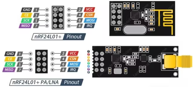
2/A7 on FZ goes to MOSI/6 on NRF24
3/A6 on FZ goes to MISO/7 on NRF24
4/A4 on FZ goes to CSN/4 on NRF24
5/B3 on FZ goes to SCK/5 on NRF24
6/B2 on FZ goes to CE/3 on NRF24
8/GND on FZ goes to GND/1 on NRF24
9/3V3 on FZ goes to VCC/2 on NRF24
IRQ/8 is left disconnected on NRF24
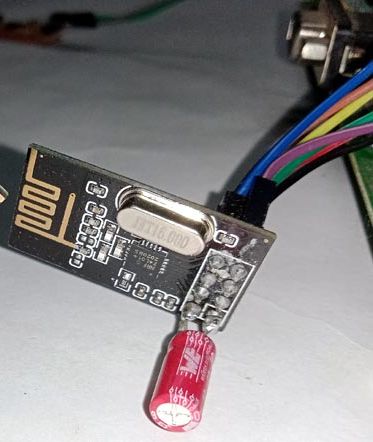
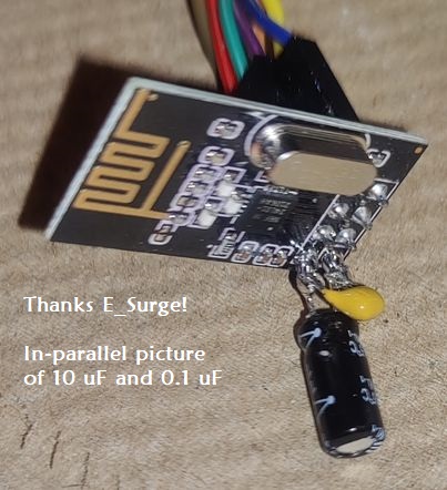
If the nRF model is acting a bit flakey, try adding a capacitor to the vcc/gnd lines! I've not tried the Plus model so it may have a bigger need for a cap. Otherwise, I haven't had any major issues. Anything from a 3.3 uF to 10 uF should do. (Watch your positive/negative placement! Negative to ground.) I learned if you wanna get fancy, include a 0.1 uF cap in parallel. The 3.3 uF to 10 uF will respond to slow freq changes while the 0.1 uF will respond to the high freq switching spikes that the larger one cannot. That said, a single 10 uF will likely suffice for the Mousejack attack. ¯\\\_(ツ)_/¯
# NRF24L01+ (B) - 10-pin

Thank you to [Amec0e](https://github.com/amec0e) for the information on the newer NRF24L01 (B)!
NRF24: 1 (CE) to FZ 6 (B2)
NRF24: 2 (SCK) to FZ 5 (B3)
NRF24: 3 (CSN) to FZ 4 (A4)
NRF24: 4 (MOSI) to FZ 2 (A7)
NRF24: 6 (MISO) to FZ 3 (A6)
NRF24: 7 or 8 (GND) to FZ GND (8 or 11 or 18)
NRF24: 9 or 10 (VCC) to FZ 9 (3v3)
# ESP32-WROOM
NOTE: Use `old_hardware.bin` if flashing Marauder onto the ESP32-WROOM (thanks wyldgoat!)


## ESP32 / ESP32-WROOM Pinout to Flipper Zero
(Thanks [E_Surge](https://github.com/ESurge) and wyldgoat for guidance!)
NOTE: Make sure you're using at least an ESP32 v2 or above for full functionality! [Good read](https://blog.spacehuhn.com/esp32-deauther).
Running an ESP32 single-core and want Marauder? You've gotta head over to [V0lk3n's write-up](https://github.com/V0lk3n/Flipper-ESP32-Solo-Marauder)!
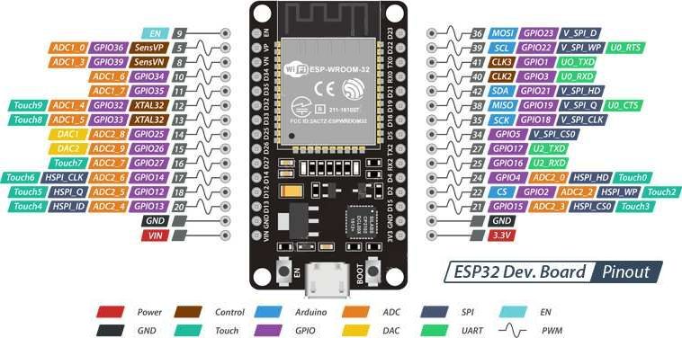
ESP32: 3 (RX0) -> FZ: 13 or 15 (these are TX pins)
ESP32: 1 (TX0) -> FZ: 14 or 16 (these are RX pins)
ESP32: GND -> FZ: 8 or 11 or 18 (GND)
ESP32: 5V -> FZ: 1 (5V) ***OR*** ESP32: 3.3V -> FZ: 9 (3.3V)
*NOTE: Make sure to enable 5v under GPIO on the Flipper*
Switch between UART Pins 13/14 and 15/16 setting in FlipperZero
`(GPIO -> USB-UART Bridge -> LEFT -> UART Pins)`
# ESP8266
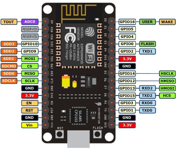
If you have the ESP8266 and are looking to use a wifi deauth, check out [speexvocon's](https://github.com/Speexvocon/FlipperZeroESPexpansion) easy [web flasher](https://github.com/Speexvocon/FlipperZeroESPexpansion#programming-the-module)!
If you're looking to give another deauther a try, [check out HEX0DAYS repo over here](https://github.com/HEX0DAYS/FlipperZero-PWNDTOOLS).
## ESP8266 Pinout to Flipper Zero
(Thanks PixelHerstel for additional guidance!)
ESP8266: 1 (TX0) -> FZ: 14 or 16 (these are RX pins)
ESP8266: 3 (RX0) -> FZ: 13 or 15 (these are TX pins)
ESP8266: 5 -> FZ: 7
ESP8266: 6 -> FZ: 6
ESP8266: 7 -> FZ: 5
ESP8266: 8 -> FZ: 4
ESP8266: VIN -> FZ: 1
ESP8266: GND -> FZ: 8 or 11 (GND)
FZ: 16 -> FZ: 18 (yes, FZ to FZ)
ESP8266: 5V -> FZ: 1 (5V)
*NOTE: Make sure to enable 5V under GPIO on the Flipper*
***OR*** ESP32: 3.3V -> FZ: 9 (3.3V) though this can have issues...
Switch between UART Pins 13/14 and 15/16 setting in FlipperZero
`(GPIO -> USB-UART Bridge -> LEFT -> UART Pins)`
A visual pinout can be seen in [this PDF](https://github.com/UberGuidoZ/Flipper/blob/main/GPIO/ESP8266_WIFI_Schematic.pdf), too.
# ESP32-S2 WROVER
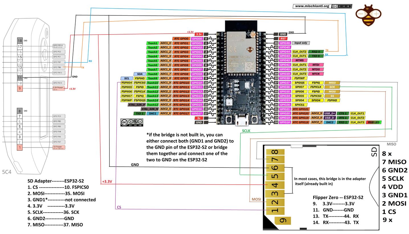
## ESP32-S2 WROVER Pinout (thanks max_fpv_austria!)
ESP32: 44 (RX0) -> FZ: 13 or 15 (these are TX pins)
ESP32: 43 (TX0) -> FZ: 14 or 16 (these are RX pins)
ESP32: GND -> FZ: 8 or 11 or 18 (GND)
ESP32: 3.3V -> FZ: 9 (3.3V)
Switch between UART Pins 13/14 and 15/16 setting in FlipperZero
`(GPIO -> USB-UART Bridge -> LEFT -> UART Pins)`
Picture includes wiring pinout for the SD card mod too!
# ESP32-CAM (Camera)
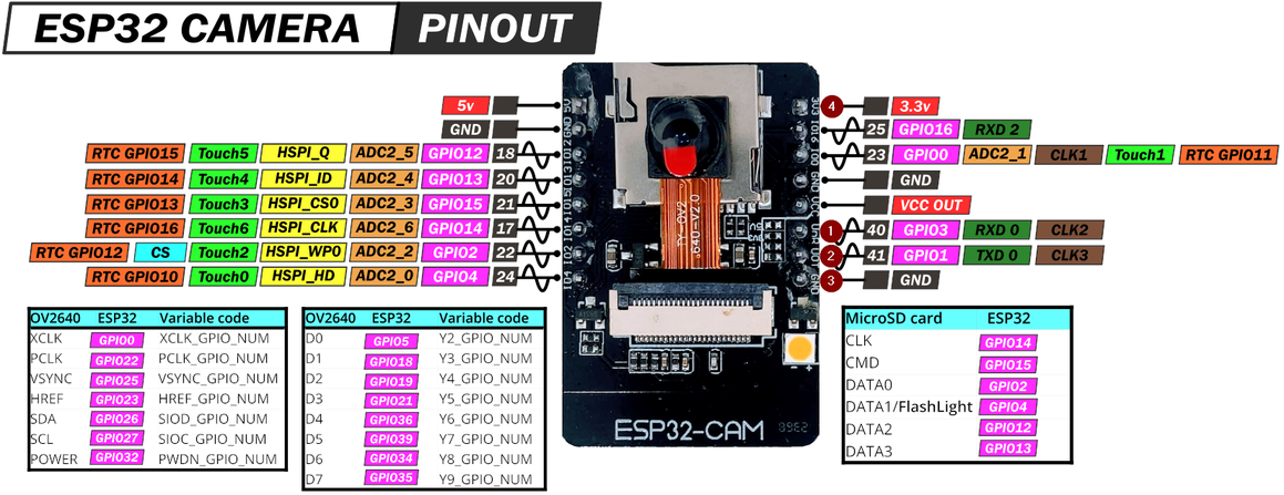
## ESP32-CAM Pinout to Flipper Zero
CAM32: 1 (RX0) -> FZ: 13 or 15 (these are TX pins)
CAM32: 2 (TX0) -> FZ: 14 or 16 (these are RX pins)
CAM32: 3 (GND) -> FZ: 8 or 11 or 18 (GND)
CAM32: 4 (3.3V) -> FZ: 9 (3.3V) ***OR*** ESP32: 5V -> FZ: 1 (5V)
# LoRa ESP32 Wifi (Wifi + Bluetooth + LoRa 433 MHz)
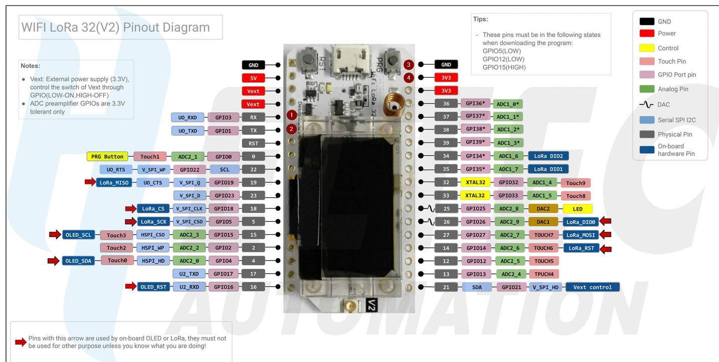
## LoRa ESP32 Wifi Pinout to Flipper Zero
LoRa32: 1 (RX0) -> FZ: 13 or 15 (these are TX pins)
LoRa32: 2 (TX0) -> FZ: 14 or 16 (these are RX pins)
LoRa32: 3 (GND) -> FZ: 8 or 11 or 18 (GND)
LoRa32: 4 (3.3V) -> FZ: 9 (3.3V)
Switch between UART Pins 13/14 and 15/16 setting in FlipperZero
`GPIO -> USB-UART Bridge -> LEFT -> UART Pins`
# Raspberry Pi Zero UART

## Raspberry Pi Zero : Prerequisite
Mount your SD Card to your computer and add the following line at the end of `/boot/config.txt` file.
`enable_uart=1`
Additionally you can look at the baudrate in the `/boot/cmdline.txt` file, which should be `115200` by default.
## Raspberry Pi Zero : Pinout to Flipper Zero
```
PiZero: 4 (5V) -> FZ: 1 (5V)
PiZero: 6 (GND) -> FZ: 11 (GND)
PiZero: 8 (UART0_TXD) -> FZ: 14 (RX)
PiZero: 10 (UART0_RXD) -> FZ: 13 (TX)
```
## HC-SR04 Ultrasonic Distance Sensor
Plugin by Sanqui: https://github.com/Sanqui/flipperzero-firmware/blob/hc_sr04/applications/hc_sr04/hc_sr04.c
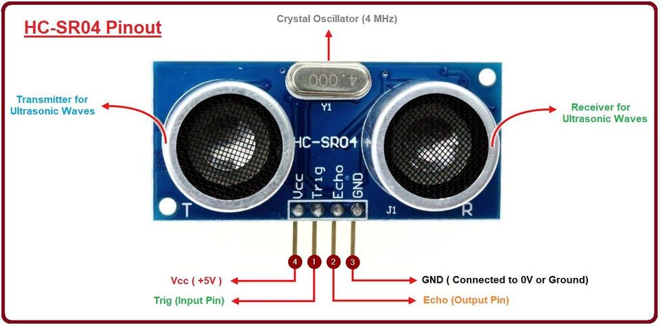
```
HC-SR04: 1 (RX0) -> FZ: 13 or 15 (these are TX pins)
HC-SR04: 2 (TX0) -> FZ: 14 or 16 (these are RX pins)
HC-SR04: 3 (GND) -> FZ: 8 or 11 or 18 (GND)
HC-SR04: 4 (5V) -> FZ: 1 (5V)
Switch between UART Pins 13/14 and 15/16 setting in:
Flipper -> GPIO -> USB-UART Bridge -> LEFT -> UART Pins
```
-----
## NMEA 0183 GPS
https://github.com/ezod/flipperzero-gps
```
GPIO pins 9 (3.3V), 11 (GND), 13 (TX), and 14 (RX)
```

-----
## i2c Tools (by NaejEL)
```
C0 -> SCL / C1 -> SDA / GND -> GND | 3v3 logic levels only!
```
https://github.com/NaejEL/flipperzero-i2ctools
-----
## HTU21D / SI7021 Temperature Sensor
```
GPIO pins 9 (3.3V), 11 (GND), 15 (sda), and 16 (scl)
```
https://github.com/Mywk/FlipperTemperatureSensor

-----
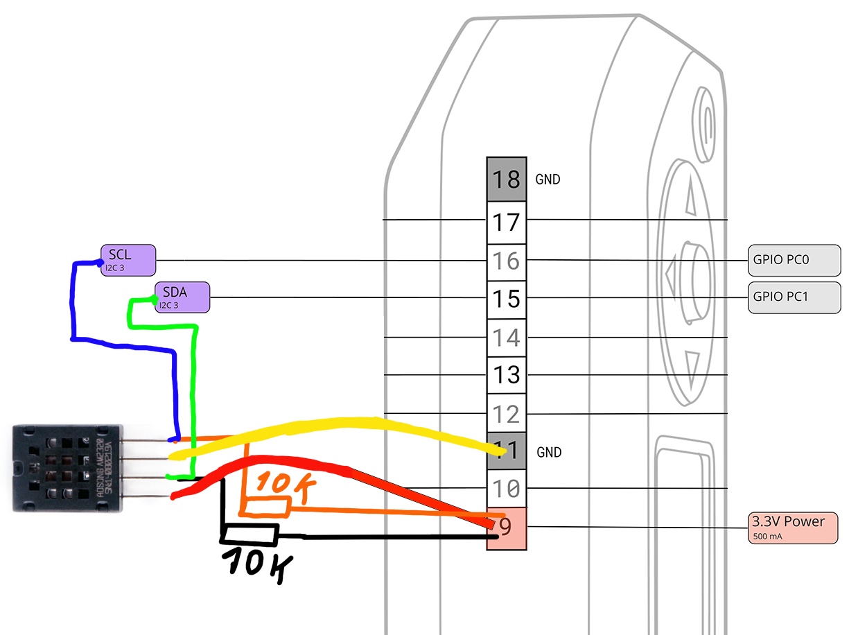
## AM2320/AM2321 Temp. Sensor
```
GPIO pins 9 (3.3V), 11 (GND), 15 (sda), and 16 (scl)
```
https://github.com/xMasterX/AM2320_Flipper_Plugin
-----
## DHT11/22 Temp. Sensor
```
VCC (none, +, VCC, red wire) 1 (5V) or 9 (3V3)
GND (-, GND, black wire) 8, 18 (GND)
DATA (OUT, S, yellow wire) 2-7, 10, 12-17 (to choose from)
```
https://github.com/quen0n/FipperZero-DHT-Monitor
-----
I've had so many asking for me to add this.
 
**BTC**: `3AWgaL3FxquakP15ZVDxr8q8xVTc5Q75dS`
**BCH**: `17nWCvf2YPMZ3F3H1seX8T149Z9E3BMKXk`
**ETH**: `0x0f0003fCB0bD9355Ad7B124c30b9F3D860D5E191`
**LTC**: `M8Ujk52U27bkm1ksiWUyteL8b3rRQVMke2`
So, here it is. All donations of *any* size are humbly appreciated.
 
Donations will be used for hardware (and maybe caffeine) to further testing!
